


1. Heat Pump Reversing Valve Structure
The heat pump reversing valve (HVAC reversing valve) is mainly used in heat pumps. Since there are mainly four pipes connected to it in structure, it is often called a four-way reversing valve. Its role is to change the function of the heat pump by changing the flow direction of the refrigerant in the system to achieve switching of cooling, heating or defrosting.
The heat pump reversing valve is composed of two parts: the solenoid pilot valve and the four-way reversing valve. Among them, the solenoid pilot valve is composed of a solenoid coil and a pilot valve. The four-way reversing valve is composed of a reversing valve and four pipes. The solenoid pilot valve and the four-way reversing valve are connected by four capillary tubes, as shown below.

2. Working Principle of Heat Pump Reversing Valve: Cooling and Heating Modes
After understanding the structure of the heat pump reversing valve, it is very puzzling how these accessories combined achieve the switching of cooling and heating modes. Let's take a look at how the heat pump reversing valve switches between cooling and heating modes.
2.1 Cooling Cycle (Coil De-energized State)

When the solenoid coil is in the de-energized state state (i.e., heat pump in cooling state), the pilot slide valve ① moves to the left driven by the compression spring ②, and the high-pressure fluid enters the capillary tube ③ and then enters the right side piston chamber ④.
On the other hand, the fluid in the left side piston chamber ⑥ is connected to the S pipe and is sucked out by the compressor. This creates a pressure difference at both ends of the piston, and the piston and the main slide valve ⑤ move to the left, making the E and S pipes connected, and D and C pipes are connected, thus forming a cooling cycle. The refrigerant flows as shown in the figure.
2.2 Heating Cycle (Coil Energized State)

When the solenoid coil is in the energized state (i.e., heat pump in heating state), the pilot slide valve ①, under the action of the magnetic force generated by the solenoid coil, overcomes the elastic force of the compression spring ② and moves to the right side. The high-pressure fluid enters the capillary tube ③ and then enters the left side piston chamber ⑥.
On the other hand, the fluid in the right piston chamber ④ is connected to the S pipe and is sucked out by the compressor. This causes a pressure difference between the two ends of the piston. The piston and the main slide valve ⑤ move to the right, so that the C and S pipes are connected, and D and E pipes are connected, thus forming a heating cycle. The refrigerant flows as shown in the figure.
3. Fault Analysis of Heat Pump Reversing Valve
There are four main types of common heat pump reversing valve failures in after-sales: bad coil, no reversing, internal refrigerant leakage and external refrigerant leakage. So, what are the causes and solutions for each fault? Let’s discuss it together next!
3.1 Solenoid Coil Damaged
1. Reasons
Due to unstable power supply voltage, nonstandard installation of the solenoid coil during production, failure to align the valve core, and loosening of the fixing screws during installation or operation, it may cause the pilot slide valve core to be stressed unevenly, and may also cause the solenoid coil to be damaged due to excessive heat generation.
2. Fault Detection
First check whether the solenoid coil terminals are well connected to the motherboard, then measure whether the mainboard is supplying power to the reversing valve solenoid coil normally, and then use a multimeter to check whether the resistance and insulation of the solenoid coil are normal (picture below). If the resistance is obviously too small or too large, and the insulation of the shell is damaged, these indicate that the solenoid coil is bad.
Generally, the resistance of the reversing valve solenoid coil is between 0.5-2KΩ. If it is obviously too small or too large, it indicates a short circuit or open circuit between the turns of the coil.

3. Solution
Replace the coil with one having the same specifications.
3.2 No Reversing (Mechanical Failure)
1. Reasons
① Impurities enter the reversing valve, causing the slide valve to get stuck.
② External deformation of valve body is mainly due to the collision caused by external forces during installation or transportation.
③The pressure difference between the two ends of the reversing valve piston is small, causing no reversing. The possible reasons include too low outside temperature, refrigerant leakage, and insufficient refrigerant flow when the compressor is started.
2. Fault Detection
First, measure the pressure of the refrigeration system to ensure that the refrigerant is sufficient; then listen for a suction sound when the heat pump switches for cooling or heating. If there is no obvious reversing sound when reversing, it indicates that the reversing valve may be stuck. Use a small wooden stick to gently knock the valve body to see if it can restore reversing.

3. Solution
If there is a shortage of the refrigerant, detect the leakage and replenish it. If the valve is stuck and cannot be restored, it must be replaced.
3.3 Internal Refrigerant Leakage
1. Reasons
The internal refrigerant leakage of the reversing valve means that the refrigerants in the high and low pressure pipes of the reversing valve are mixed together. Regardless of whether it is cooling or heating mode, the cold suction pipe is not cold, the hot discharge pipe is not hot, and the temperatures of the two pipes tend to be the same. The main reasons are insufficient reversing and poor sealing of the slider.
2. Fault Detection
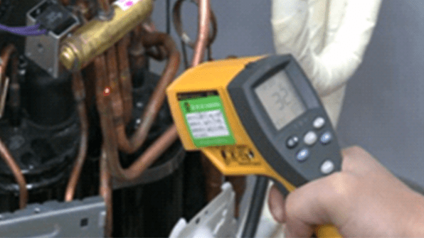
Use a temperature measurement instrument to measure the temperature difference between suction (5~15℃ in rated cooling mode) and discharge (60~90℃ in rated cooling mode); if the error is not obvious, it indicates internal refrigerant leakage in the reversing valve. If there is no temperature measuring instrument, You can judge by "touching" with your hands.
3. Solution
If repeated reversing cannot be restored, the valve must be replaced.
3.4 External Refrigerant Leakage
1. Causes of failure
Pipe cracks and leaks occur due to transportation and installation, after-sales maintenance and welding, pipeline vibration and other reasons.
2. Fault Detection
Cracks and leaks will cause no cooling and heating, and no reversing. The detection method is the same as the aforementioned no reversing.
3. Solution
Reweld or replace the valve.
