


Hydraulic valves (hydraulic control valves) are hydraulic components used to control and regulate the pressure, flow and direction of fluid flow in hydraulic systems. According to different uses and working characteristics, hydraulic valves can be divided into three types:
●Hydraulic pressure control valves (including relief valves, pressure reducing valves, sequence valves, unloading valves),
● Hydraulic flow control valves (including throttle valves, speed control valves, diverter valves, combiner valves, divider-combiner valves)
●Hydraulic directional control valve (including solenoid operated directional control valve, manual directional control valve, check valve, electro-hydraulic directional control valve).
1. Types of Hydraulic Flow Control Valves
Hydraulic flow control valves are suitable for water systems and hydraulic systems that require flow control. They are especially suitable for flow control of non-corrosive liquid media in the heating and air conditioning applications.
Flow control valves are divided into five types: hydraulic throttle valve, speed control valve, diverter valve, combiner valve, divider-combiner valve valve.
1.1 Hydraulic Throttle Valve
A hydraulic throttle valve does not have a flow negative feedback function and cannot compensate for the speed instability caused by load changes. It is generally only used in applications where load changes are not large or speed stability requirements are not high.

1.2 Speed Control Valve
When the load pressure changes, the speed control valve can maintain the inlet and outlet pressure difference of the hydraulic throttle valve at a constant value. In this way, after the throttling area is set, no matter how the load pressure changes, it can maintain the flow rate through the hydraulic throttle valve unchanged, thereby stabilizing the movement speed of the actuator.
1.3 Hydraulic Diverter Valve
The function of the diverter valve is to supply the same oil flow rate to two or more actuators from the same oil source in the hydraulic system, or to supply according to a certain ratio to achieve that the speeds of the two actuators remains synchronous or proportional.
1.4 Combiner Valve
The function of the combiner valve is to collect equal or proportional oil return volume from the two actuators to achieve speed synchronization or a fixed ratio relationship between them.
1.5 Flow Divider-Combiner Valve
The flow divider-combiner valve has the functions of both a diverter valve and a combiner valve.

2. Types of Hydraulic Pressure Control Valves
Hydraulic pressure control valves can be divided into: relief valves, pressure reducing valves, sequence valves, and unloading valves.
2.1 Hydraulic Pressure Relief Valve
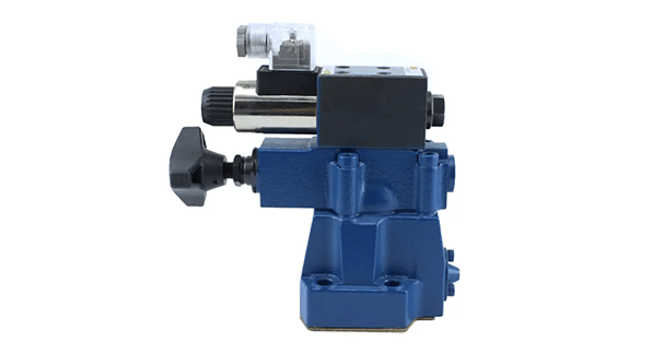
The relief valve is a hydraulic pressure control valve that mainly plays the role of constant pressure relief, pressure stabilization, system unloading and safety protection in the hydraulic system. Relief valves generally have two structures: direct-acting and pilot-operated relief valves.
The main requirements for the relief valve are: large pressure regulating range, small pressure regulating deviation, small pressure oscillation, sensitive action, large overload capacity and low noise.
2.2 Hydraulic Pressure Reducing Valve
The pressure reducing valve is a valve that reduces the inlet pressure to a required outlet pressure through adjustment, and relies on the energy of the medium itself to automatically maintain a stable outlet pressure.

2.3 Hydraulic Sequence Valve
A sequence valve is a valve that controls the action sequence of actuators based on the pressure of the circuit in a system with two or more branch circuits.
According to the working principle and structure, sequence valves are divided into two types: direct-acting and pilot-operated;
According to the pressure control method, sequence valves are divided into internal control and external control.
2.4 Unloading Valve
The unloading valve is a common hydraulic control component, mainly used to control the flow of liquid in the hydraulic system. It usually consists of a spring device and a piston, and controls the liquid flow by controlling the movement of the piston.
The working principle of the unloading valve is very simple. When the pressure in the hydraulic system reaches the set value, the unloading valve opens and makes the liquid flow back into the pressure accumulator to reduce the pressure in the system.
This can protect the safety of the hydraulic system and reduce the energy consumption of the system. At the same time, the unloading valve can also play a buffering role, reducing pressure shock in the system and extending the service life of system components.
2.5 Difference between Relief Valve, Pressure Reducing Valve and Sequence Valve
Simply put, the function of the relief valve is to stabilize the inlet pressure of the valve, the pressure reducing valve is to stabilize the outlet pressure of the valve, and the sequence valve is to connect to (when the sequence valve is working) or cut off (when the sequence valve is closed) a certain oil line.
3. Types of Hydraulic Directional Control Valves
Hydraulic directional control valves can be divided into: solenoid operated directional control valves, manual directional control valves, check valve, electro-hydraulic directional control valve.
3.1 Solenoid Operated Directional Control Valve
The solenoid operated directional control valve is a control valve that uses the thrust of an electromagnet to push the movement of the valve core to change the direction of fluid flow. Because it can be controlled by signals from push button switches, limit switches, pressure relays, etc., it is easy to operate and achieve automation, and has a wide range of applications.

3.2 Manual Directional Control Valve
It changes the flow direction of hydraulic oil by manually rotating the valve core, thereby achieving control of various parts of the hydraulic system. Hydraulic manual directional control valves have the advantages of simple structure, convenient operation, installation and maintenance, etc., so it has been widely used in engineering machinery, metallurgy, machine tools and other fields.
3.3 Hydraulic Check Valve
Hydraulic check valve is also called one-way valve, used in hydraulic systems to prevent reverse flow of the oil.
3.4 Pilot Operated Check Valve
The hydraulically controlled one-way valve is a valve that can reverse the flow of the one-way valve by controlling the fluid pressure.
3.5 Electro-Hydraulic Directional Control Valve
It is composed of a solenoid spool valve and hydraulic spool valve. When the liquid flow rate is large, the hydraulic power needed is large for a simple solenoid operated directional control valve, and the corresponding control electromagnet is large and bulky. If the electro-hydraulic type is used, the volume is relatively small when the flow rate is large.

