


In order to protect the environment, most excavators are now using EFI systems (referring to electronic fuel injection systems). You may often encounter various error codes, which are mostly caused by sensor or solenoid valve failure. The following is the location diagram and introduction of the ten sensors and solenoid valves on the excavator engine.
1. Sensors and Solenoid Valves on the Engine
1.1 EGR Valve

Common error codes: P0405, P0406, P0407
Location: It is a silver cylinder-shaped component located on the side of the engine near the counterweight.
Function: The EGR (exhaust gas recirculation) valve is a proportional solenoid valve with variable opening degrees and is controlled by ECU. The ECU makes a judgment based on information such as engine speed, water temperature, common rail pressure, etc., and adjusts the opening of the EGR valve to allow an appropriate amount of exhaust gas to enter the combustion chamber again. This achieves the purpose of reducing the content of nitrogen oxides in emissions without affecting engine power.
1.2 Injector Connector

Common error codes: P0201, P0202, P0203, P0204, P0205, P0206
Location: On the engine cylinder cover.
Function: It is used to maintain the communication of control signals between the solenoid valve in the injector and the ECU. Based on the information, such as speed, water temperature, common rail pressure, etc. received from the sensors, the ECU gives instructions to the injector solenoid valve to control the injection start time and stop time, thereby controlling the speed and torque of the engine.
1.3 Fuel Rail Pressure Sensor

Common error codes: 20111, 20112, 20121, 20122
Location: Located on high voltage common rail.
Function: It is used to feed back the high-pressure diesel pressure signal in the common rail cavity to the ECU. Due to the high-pressure injection used in the common rail diesel control system, the injection pressure is more than 10 times higher than that of ordinary direct injection engines. Therefore, the ECU will monitor the diesel pressure in the common rail cavity in real time, make judgments based on the feedback pressure signal and other feedback signals, and give command signals to control units such as the injector solenoid valve, EGR solenoid valve, and SCV valve.
1.4 Oil Pressure Switch

Common error codes: 00198, 01008
Location: On the engine's oil cooler.
Function: It is a normally closed pressure switch, and detects the engine oil pressure and feeds the signal back to the CPU. After receiving the abnormal signal, the CPU will control the error to appear on the display screen and the buzzer to sound an error at the same time. If a low oil pressure signal occurs when the engine is started, in addition to errors, it will also control the engine to automatically shut down.
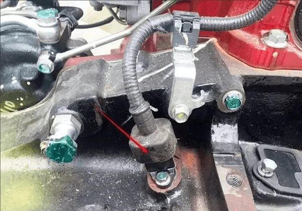
1.5 CPU Main Speed Sensor

Common error codes: G033, G043
Location: The lower edge of the flywheel.
Note: Only KOBELCO SK130 and above models have a CPU dedicated speed sensor.
Function: It is used to feed back the engine speed signal to the CPU. After receiving the feedback signal from the main speed sensor, the CPU compares it with the speed set internally in the program to determine whether the engine speed is normal and whether the engine load status is normal, and combines other feedback signals to control the engine and hydraulic system. Under abnormal conditions, it will control the hydraulic system to reduce horsepower or shut down the engine.
1.6 Boost Pressure Sensor

Common error codes: P0108, P0237
Location: On the turbocharger.
Function: It is used to feedback the suction pressure boosted by the supercharger to the ECU. After receiving the feedback signal from the boost pressure sensor, the ECU determines whether the intake system is normal and combines other feedback signals to control the engine's injection volume, EGR opening, SCV valve, etc. Under abnormal conditions, it will control the engine to reduce output.
1.7 SCV Valve
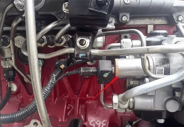
Common error code: P0628
Location: Located on the diesel pump.
Function: The SCV valve (suction control valve) is used to control the inlet diesel flow of the engine diesel fuel supply pump. It is an inversely proportional solenoid valve controlled by an ECU. The ECU receives signals such as engine speed, water temperature, common rail pressure, suction pressure, etc., sends command current to the SCV valve and controls its opening to control the flow of diesel entering the fuel supply pump and adjust the common rail pressure. Abnormal conditions may cause the engine output to drop or even shut down.
1.8 Fuel Temperature Sensor

Common error codes: P0182, P0183, P0187, P0188
Location: Located on the diesel pump, next to the SCV valve.
Function: The temperature sensor signal controls the fuel heater and protects the diesel generator. If the sensor fails, it will affect engine performance.
1.9 Engine Speed Sensor
Main engine speed sensor
Common error codes: P0335, P0336
Location: The lower edge of the flywheel.
Secondary engine speed sensor
Common error codes: P0340, P0341
Location: On the engine cylinder cover.

Function: The main and secondary engine speed sensors are jointly used to feedback engine speed, crankshaft angle, and camshaft angle signals to the ECU, so that the ECU can correctly judge timing information. The two sensors verify each other. If one sensor loses the feedback signal, the engine can still be used with reduced output. If both sensors lose signals at the same time, the engine will not start.
