


The article describes the structure and working principle of the three-way two-position solenoid valve used in refrigerators and the four-way reversing valve used in heat pumps (i.e. heat pump reversing valve).
1. 3-Way 2-Position Solenoid Valves for Refrigerators
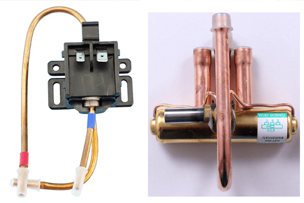
The refrigerator solenoid valve (taking the three-way two-position valve as an example) is a valve controlled by an electrical signal and is usually used in refrigeration systems such as refrigerators and freezers. Its main function is to change the refrigerant flow direction, control the temperature of different compartments, and optimize the refrigeration structure to achieve ideal setting requirements and facilitate different user needs.
Since the three-way two-position direct-acting solenoid valve has the characteristics of zero-pressure start, good sealing performance, fast opening speed, good reliability, and long service life, it is not only used in dual-temperature dual-control, multi-temperature multi-control refrigerators, also widely used in medical equipment, air compressors, instrumentation, metallurgy, pharmaceutical and other industries.

1.1 Working Principle of 3-Way 2-Position Solenoid Valve
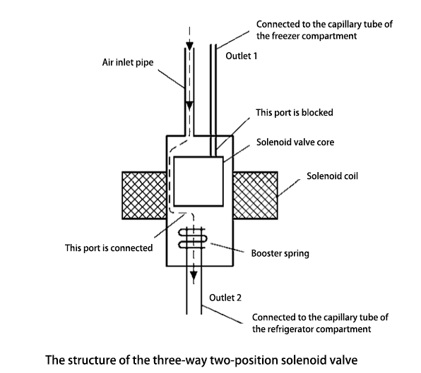
As shown in the figure below, when the coil of the three-way two-position valve is not energized, the valve core is in the original position, so that outlet 1 is closed, outlet 2 is opened, and the evaporator in the refrigerator compartment works.
After the coil is energized, the magnetic field generated will attract the valve core, closing outlet 2, leaving outlet 1 open, and only the refrigerator evaporator works. In this way, through its control, it meets the cooling needs of the refrigerator and freezer compartments.
2. 4-Way Reversing Valve for Heat Pumps
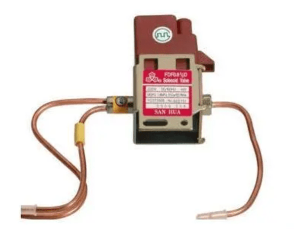
The four-way reversing valve is also called four-way solenoid valve, four-way valve, and reversing valve. Only heat pumps are equipped with four-way reversing valves. The appearance of a typical four-way reversing valve is as shown in the figure below.

The four-way reversing valve is mainly to change the function of the indoor and outdoor heat exchangers by switching the direction of high-pressure and high-temperature refrigerant discharged from the compressor to achieve cooling or heating.
2.1 Structure of 4-Way Reversing Valve
As shown in the figure below, the four-way reversing valve consists of a pilot valve and a reversing valve. Among them, the pilot valve consists of two parts: valve body and solenoid coil. The valve body is equipped with springs, valve cores, and an armature inside, which is connected to the reversing valve through three capillary tubes C, D, and E.
The valve body of the reversing valve is equipped with a semicircular slider and two pistons with small holes. There are 4 pipe ports outside the valve body, which are respectively connected with the discharge pipe and suction pipe of the compressor in the refrigeration system, and indoor and outdoor heat exchangers.

2.2 Working Principle of 4-Way Reversing Valve
(1) Cooling Cycle

As shown in the figure (a) above, when the heat pump is set to the cooling state, the electrical system does not provide driving voltage (pulse signal) to the coil of the pilot valve, the coil cannot generate a magnetic field, and the armature does not move.
At this time, the elastic force of spring 1 is greater than that of spring 2, pushing spool A and B to move to the left together, so the capillary tube D is blocked by spool A, and the capillary tubes C and E are connected.
Since the piston 2 of the reversing valve is connected to the return pipe of the compressor through the C pipe, the pilot valve, and the E pipe, the piston 2 drives the slider to move left due to the pressure reduction on the left side, allowing the pipe port 4 to be connected with the pipe port 3 and pipe port 2 to be connected to pipe port 1. At this time, the indoor heat exchanger acts as an evaporator and the outdoor one acts as a condenser.
In this way, the high-pressure and high-temperature gas discharged from the compressor enters the outdoor heat exchanger through the pipes 4 and 3 of the reversing valve, passes it to dissipate heat, and then enters the indoor heat exchanger through the capillary tube. Then the refrigerant returns to the compressor through pipe 1 and pipe 2 after using the indoor evaporator to absorb heat and vaporize. At this point, a cooling cycle process ends.
(2) Heating Cycle

As shown in the figure (b) above, when the heat pump is set to the heating state, the electrical system provides a driving voltage to the coil of the pilot valve, and the coil generates a magnetic field, causing the armature to move to the right.
Valve core A and B move to the right together under the action of the armature and spring 2. The capillary tubes D and E are connected, while the capillary tube C is blocked by valve core B.
Since the piston 1 of the reversing valve is connected to the return pipe of the compressor through the D pipe, the pilot valve, and the E pipe, the piston 1 drives the slider to move to the right due to the pressure reduction on the right side, allowing the pipe port 4 to be connected with the pipe port 1 and pipe port 3 to be connected to pipe port 2. At this time, the indoor heat exchanger acts as a condenser and the outdoor one acts as an evaporator.
In this way, the high-pressure and high-temperature gas discharged from the compressor enters the indoor heat exchanger through the pipes 4 and 1 of the reversing valve, passes it to start dissipating heat, and then enters the outdoor heat exchanger after being throttled and decompressed by the capillary tube. And then the refrigerant returns to the compressor through the pipe port 3 and pipe port 2 after using the outdoor heat exchanger to absorb heat and vaporize. At this point, a heating cycle process ends.
