


Figure 1: LG refrigerator compressor NS30LAEG
For a refrigerator product, the most core part is the compressor. If the refrigerator does not have a compressor with good quality and technology, it cannot be called a refrigerator product with excellent quality and high cost performance.
At present, there are many refrigerators produced by big brands in the market that use high-quality compressors. The purpose is to bring better refrigerator purchase and use experience to users. Let's give you a detailed introduction to the structure and working principle of the refrigerator compressor.
1. Structure of Refrigerator Compressor
1.1 Where to Install the Refrigerator Compressor
The compressor is usually located at the bottom of the back of the refrigerator, fixed with screws, and connected to the refrigeration pipeline of the refrigerator through two pipes, that is, suction pipe and discharge pipe.
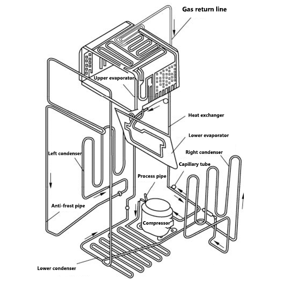
Figure 2: The installation location diagram of refrigerator components.
1.2 External Structure of Refrigerator Compressor
In different types of refrigerators, the shape of the compressor is roughly the same.
Compressor body: including two parts, compressor motor and cylinder.
Process tube: It is the pipe used by refrigerators for vacuuming, adding refrigerant, nitrogen cleaning or leak detection.
Compressor protection device: including start relay and overheat protection relay, installed above the compressor terminal.
Compressor terminals: including common terminal (C), starting terminal (S), and running terminal (R). During wiring, the three winding terminals can be distinguished according to the icons on the nameplate.
Compressor suction and discharge ports: the suction port is connected to the evaporator, and the discharge port is connected to the condenser, so that the refrigeration pipeline forms a closed path to facilitate the circulation of the refrigerant.

Figure 3: The external structure diagram of a refrigerator compressor.
The shapes of different refrigerator compressors are basically the same, and the start protection device is usually installed on the left side of the compressor, but the positions of the three pipes on the shell are different.
The compressors used in general refrigerators mostly are reciprocating compressors. Let's take the reciprocating compressor as an example to carefully study the internal structure of this type of compressor.
1.3 Internal Structure of Refrigerator Compressor
The reciprocating compressor uses the crankshaft as the main shaft, and converts the rotational motion of the motor into the reciprocating motion of the piston through the crankshaft to compress the refrigerant.
The reciprocating compressor is relatively stable in operation, low in noise, small in wear, long in service life, relatively high in energy efficiency, and excellent in comprehensive performance. With the continuous development of the machinery industry, the reciprocating compressor has been improved in many aspects.

Figure 4: Reciprocating compressor structure diagram.
With the continuous emergence of new technologies, many refrigerators have also begun to adopt new types of compressors, such as rotary compressors and inverter compressors.
Among them, the motor of the rotary compressor directly drives the rotary piston to rotate to complete the compression of the refrigerant gas. Therefore, it has the characteristics of high compression efficiency, small size, light weight, good balance performance, low noise, complete protection measures and low power consumption.
The appearance of the inverter compressor is similar to that of the ordinary compressor, but the internal motor it adopts is the frequency conversion motor, and it realizes the low power consumption operation under the control of the frequency conversion circuit.
2. How a Refrigerator Compressor Works
1. The refrigerator compressor sucks in low-temperature and low-pressure refrigerant gas from the suction port, and then compresses it.
2. The compressor compresses the refrigerant into a high-temperature and high-pressure saturated gas, which is discharged from the exhaust port.
3. The high-temperature and high-pressure saturated gas coming out of the exhaust port passes through the condenser to dissipate heat and cool down.
4. When the liquid refrigerant passes through the capillary tube (or expansion valve), it is contained, so the pressure of the refrigerant coming out decreases, and the temperature drops.
5. Then the refrigerant enters the evaporator, undergoes heat exchange and gasification in the evaporator, becomes a high-temperature and low-pressure gaseous refrigerant and returns to the compressor to continue the cooling cycle. The refrigerant absorbs the heat of the air and food in the refrigerator through evaporation and gasification to keep the food fresh and frozen.

Figure 5: Refrigerator compressor working process diagram.
2.1 Working Principle of Reciprocating Compressor
The commonly used compressors in refrigerators are reciprocating compressors, and the reciprocating compressors use the electric motor to drive the piston to do reciprocating motion in the cylinder to realize the compression of refrigerant gas.
1. When the compressor motor winding is energized, the motor drives the crankshaft to rotate.
2. The connecting rod and piston move downward.
3. The pressure in the cylinder decreases. When the pressure in the suction port is much higher than the pressure in the cylinder, under the action of the pressure difference, the suction valve opens and the refrigerant enters the cylinder.
4. With the continuous rotation of the crankshaft, when the connecting rod and piston move to the lowest position, they return and move upward.
5. The volume of the cylinder gradually decreases, and the pressure in the cylinder gradually increases accordingly. When the pressure in the cylinder exceeds the pressure of the suction port, the suction valve is closed.
6. As the volume of the cylinder gradually shrinks, the refrigerant gas in the cylinder is compressed, and the pressure of the gas continues to rise. When the pressure in the cylinder is much greater than the pressure in the exhaust port, the exhaust valve is opened under the action of the pressure difference.
7. The gas in the cylinder is discharged through the exhaust valve and enters the condenser through the exhaust port.
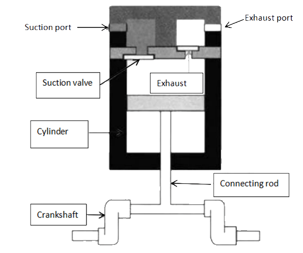
Figure 6: Reciprocating compressor structure and working process diagram.
2.2 Working Principle of Inverter Compressor
Inverter compressors mostly adopt a rotary structure, and the compression method of a rotary compressor is different from that of a reciprocating compressor. The rolling piston (rotary piston) of the rotary compressor divides the cylinder into two parts, the compression chamber and the suction chamber, and the electric motor directly drives the eccentric shaft to rotate, so that the rolling piston rotates along the inner wall of the cylinder to do the loop action of suction, compression and exhaust.
2.3 Driving Modes of Refrigerator Compressor: Fixed Speed Compressor VS Inverter Compressor
Different types of compressors in refrigerators are all driven by electric motors, but the difference is the type and driving method of the electric motors.
Wherein, the fixed speed motor (normal motor) is driven by a fixed-frequency driving method, and the compressor using this type of motor is called a fixed speed compressor. Since the power supply frequency and voltage value of the fixed speed compressor are fixed, the motor rotation speed in the fixed speed compressor is fixed.

Figure 7: Working circuit diagram of fixed speed compressor.
The variable speed motor is driven by variable frequency drive, and the compressor using this type of motor is called variable speed compressor (inverter compressor).
Because the frequency and amplitude of the power supply are variable, the motor rotation speed in the inverter compressor is alterable. The frequency conversion circuit provides a variable frequency drive signal for the variable speed compressor.
Related Info
Diagnosis and Troubleshooting of Refrigeration Compressor Failure13 Reasons Why Your Samsung Refrigerator Not Cooling (The Latest Version)
14 Common Ice Maker Problems and How to Fix Them
How a Refrigeration Compressor Works
4 Types of Safety Protection for Refrigeration Compressors (9 Common Protection Devices for Refrigeration Compressors)
