


There are four main components in the refrigeration system, namely compressor, condenser, throttling device (such as capillary tube, expansion valve), evaporator. This article introduces the functions and working principles of the four major components of the refrigeration system and other related components.

Figure 1: 4 main components of refrigeration system.
1. Compressor
A compressor is a driven fluid machine that elevates the gas pressure from low to high, and is the heart of the refrigeration system. Driven by the operation of the electric motor, it sucks low-temperature and low-pressure refrigerant gas from the suction pipe, compresses the gas through the compression mechanism (such as piston), and discharges high-temperature and high-pressure refrigerant gas through the exhaust pipe to provide power for the refrigeration cycle.
Refrigeration compressors mainly include scroll compressors, reciprocating piston compressors, screw compressors, and centrifugal compressors. According to the structure, refrigeration compressors can be divided into hermetic compressors, semi-hermetic compressors and open compressors.
2. Condenser
The condenser is a kind of heat exchanger, which can convert gas or vapor into liquid, and transfer the heat in the tube to the air near the tube in a very fast way. The working process of the condenser is an exothermic process, so the temperature of the condenser is relatively high when it is working.
3. Throttling Device

Figure 2: The theoretical cycle flow diagram of single-stage compression refrigeration.
Throttle mechanisms mainly include capillary tubes, thermal expansion valves, and electronic expansion valves. Home air conditioners and refrigerators mostly use capillary tubes; cold storage and central air conditioners mostly use thermal expansion valves.
The thermal expansion valve controls the flow of liquid refrigerant from the condenser to the evaporator. It keeps the superheat at the outlet of the evaporator at a certain level, preventing liquid refrigerant from leaving the evaporator and entering the compressor. Once liquid refrigerant enters the compressor, a liquid hammer occurs. This condition must be prevented to avoid damage to the compressor.
3.1 Working Principle of Thermal Expansion Valve
In the figure below, Pb - sensing bulb pressure, Pe - evaporation pressure, Ps - spring pressure, when Pb = Ps+Pe, the diaphragm does not move.

Figure 3: Working principle diagram of thermal expansion valve.
When Pb rises, causing Pb > Ps+Pe, the diaphragm moves down, the valve opens, and more refrigerant flows into the evaporator.
When Pb drops, resulting in Pb < Ps+Pe, the diaphragm moves up, the valve closes, and the refrigerant flowing into the evaporator decreases.
4. Evaporator
The evaporator is a very important part of the four major components of the refrigeration system. The low-temperature condensed liquid exchanges heat with the outside air through the evaporator, and absorbs heat through vaporization to achieve the effect of refrigeration.
The evaporator is mainly composed of two parts: a heating chamber and an evaporation chamber. The heating chamber provides the heat needed for evaporation to the liquid, which promotes the boiling and vaporization of the liquid; the evaporation chamber completely separates the gas-liquid two phases.
5. Liquid Receiver
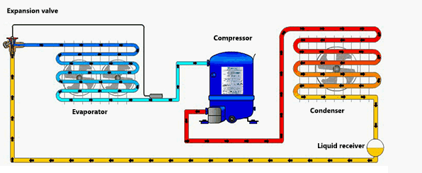
Figure 4: Installation position diagram of the liquid receiver in the refrigeration system.
Under high pressure, the compressed refrigerant vapor condenses into liquid refrigerant in the condenser. After leaving the condenser, the liquid flows through the liquid reservoir.
5.1 Functions of liquid receiver
The liquid receiver has two main functions.
1. The liquid receiver compensates for the change of the condenser liquid level caused by the load change.
When the expansion valve is opened/closed, the liquid level in the condenser will change. If there is no "extra" refrigerant in the liquid receiver, the amount of liquid in front of the expansion valve may be insufficient, causing the expansion valve to not work properly, and the entire system to become unstable.
2. The liquid receiver also serves as an additional container to help separate the liquid refrigerant from the refrigerant vapor, ensuring that what leaves the liquid receiver is pure liquid refrigerant.
6. Thermostat
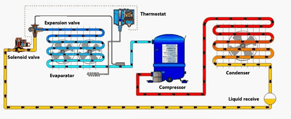
Figure 5: Installation position diagram of the thermostat in the refrigeration system.
The heat is transferred to the cold room/medium, whose temperature changes over time. So how do we maintain the temperature in the cold room?
The thermostat can sense the temperature of the cold room/medium and switch the solenoid valve on or off according to the set value, allowing or preventing the flow of refrigerant to the evaporator.
For small refrigeration systems with only one evaporator, the thermostat is usually the one that turns the compressor on or off directly.
6.1 Functions of Thermostat
It has two main functions:
1. Protection (or safety) function: To prevent the temperature from being too high or too low, such as preventing freezing.
2. Control function: Control the temperature of the refrigerated room, medium and surface.
6.2 Working Principle of Thermostat
The thermostat turns on/off the circuit when the temperature of the system/refrigerator reaches its preset value.
Condition 1 - Temperature Increasing
When the temperature of the refrigerator compartment rises, the internal pressure of the temperature sensing bulb will exceed the maximum set value. At this time, the contacts 1 and 2 are disconnected, and the contacts 1 and 4 are connected.

Figure 6: Working principle diagram of thermostat.
Condition 2 - Temperature Dropping
When the temperature of the refrigerator compartment drops, the internal pressure of the temperature sensor will be lower than the minimum set value. At this time the contacts will return to the original position, that is, contacts 1 and 4 are disconnected, contacts 1 and 2 are connected.

Figure 7: Working principle diagram of thermostat.
7. Solenoid Valve
A solenoid valve is a valve that uses electromagnetic force. It is an on/off valve that controls the flow of refrigerant based on power on and off.
Solenoid valves can be roughly divided into two categories.
Direct Acting Solenoid Valve – The solenoid valve opens/closes the valve plug directly when the valve coil is energized.
Servo Solenoid Valve – When energized or de-energized, the valve opens the pilot port allowing the main port to gradually open based on the differential pressure of diaphragm/piston (depending on whether the valve is NC or NO).
These two solenoid valves are divided into:
NC (normally Closed) type—it restricts the flow of refrigerant when not energized (normally closed), and allows the refrigerant to flow when the valve coil is energized.

Figure 8: NC (normally Closed) type solenoid valve diagram.
NO (Normally Open)type — it allows refrigerant to flow when not energized (normally open), and restricts the flow of refrigerant when the valve coil is energized.

Figure 9: NO (Normally Open) type solenoid valve diagram.
7.1 Working Principle of Solenoid Valve

Figure 10: Working principle diagram of solenoid valve in refrigeration system.
When the temperature of the refrigerator compartment rises, the pressure in the sensing bulb rises to the set value, and the power terminals 1 and 4 are connected (as shown in the picture 6), thereby opening the solenoid valve and allowing the refrigerant to flow into the evaporator.
When the temperature drops, the pressure in the sensing bulb drops to the set value. Terminals 1 and 4 are disconnected and terminals 1 and 2 are connected (as shown in the picture 7). The solenoid valve is de-energized and closed, thereby restricting the flow of refrigerant to the evaporator, and allowing the refrigerator compartment temperature to rise.
The remaining relevant refrigeration components are described in the next article.
Related Info
What Type of Compressor is Used in Domestic RefrigeratorsWhich Brand of Refrigerator is Better (6 Top Refrigerator Brands 2023)
How to Quiet a Noisy Refrigerator (11 Ways)
How to Replace Refrigerator Compressor
How to Tell if Refrigerator Compressor is Bad
