


Figure 1: Synchronous reluctance motor.
Synchronous Reluctance Motor (referred to as SynRM) is a new type of AC electric motor that forms a closed loop along the path of least magnetic reluctance and generates magnetic pulling force (i.e. reluctance torque) through the reluctance change caused by the rotor at different positions to drive the motor to rotate.
1. Working Principle and Basic Structure
1.1 How Does Synchronous Reluctance Motor Work
Synchronous reluctance motor operating principle is similar to switched reluctance motor, and it is fundamentally different from traditional AC and DC motors. It does not rely on the interaction of the stator and rotor magnetic fields to form torque like traditional motors, but follows the principle that the magnetic flux is always forms a closed loop along the path of minimum reluctance. The torque is formed by the magnetic pull generated by the change of reluctance caused by the rotor at different positions. This torque is called reluctance torque.
Figure 2 shows the schematic diagram of a certain pole structure of the SynRM rotor. The center line of the rotor salient pole, i.e., the one with small magnetic resistance, is the d-axis, and the counterclockwise over 90 electric angle is the q-axis.
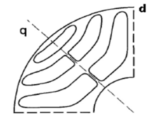
Figure 2: Schematic diagram of a certain pole structure of the SynRM rotor.
The main feature of the rotor structure of the reluctance synchronous motor is that the permeance of the horizontal axis is different from that of the vertical axis. The synchronous torque (also known as the reluctance torque) is generated by the change of the permeance to maintain the motor running at a certain synchronous speed. The generation of the reluctance torque can be described by the image of the skewed magnetic field lines in Figure 3.
When the d-axis of the rotor of the reluctance synchronous motor coincides with the centerline of the magnetic poles of the stator, the magnetic field line and the d-axis pass through the air gap and rotor in parallel. But when the rotor is in the position shown in Figure 3(b), the magnetic field lines are skewed, and the closed-loop reluctance of the magnetic field lines should be the smallest, so a tangential force F is generated. Under the action of the tangential force F, the rotor rotates in the counterclockwise direction, trying to return to the state shown in Figure 3 (a).
When the stator is three-phase or two-phase or single-phase capacitor-separated operation, a rotating magnetic field is generated in space. The rotation of the rotating magnetic field is equivalent to the stator magnetic poles N and S rotating in space in Figure 3, and the rotor does not move. Then the state shown in Figure 3(b) must appear between the stator magnetic pole and the rotor, and the tangential force F must be generated, so under the action of F , the rotor rotates in the direction of the rotating magnetic field.

Figure 3: Working principle of reluctance synchronous motor.
1.2 Basic Structure of Synchronous Reluctance Motor
The stator of SynRM generally adopts the stator structure of the traditional three-phase AC motor, and the difference is mainly in the rotor structure. There are many slots on the rotor of SynRM, and its special rotor structure realizes the huge difference in reluctance between SynRM's q and d axis magnetic circuits, showing strong salient pole effect, thereby generating a driving torque with reluctance properties.
With the development of technology, the rotor structure of SynRM is constantly evolving. At this stage, there are mainly two types of rotor structures: transversally laminated anisotropic (TLA) rotor and axially laminated anisotropic (ALA) rotor, as shown in Figure 5 and Figure 6.
The ALA structure consists of high permeability materials alternately laminated with non-magnetic conductive insulating materials along the axial direction, and has very strong salient pole effect. So the torque density and power factor are high, but the process is complicated and the manufacturing is inconvenient.
The TLA structure adopts the traditional punching and laminating process, with simple rotor structure, high mechanical strength and low production cost. However, relatively speaking, the salient pole effect is not as strong as that of the ALA structure, so the torque density and power factor are not as good as those of the ALA structure.

Figure 4: Rotor structures of TLA and ALA.
2. Features of Synchronous Reluctance Motor
Synchronous reluctance motor (SynRM) is essentially a synchronous motor with reluctance properties.
Compared with traditional DC motors, SynRM has no brushes and rings, simple and reliable, and easy to maintain.
Compared with traditional AC asynchronous motors, there is no winding on the SynRM rotor, so there is no rotor copper loss, which improves the efficiency of the motor.
Compared with the switched reluctance motor, the rotor surface of SynRM is smooth and the reluctance change is more continuous, avoiding the problems of torque pulsation and high noise during the operation of switched reluctance motors. At the same time, the stator of the SynRM is a sine wave magnetic field, which is easy to control and has a mature hardware platform, thereby reducing the cost of the drive control system.
Compared with the permanent magnet synchronous motor, there is no permanent magnet on the SynRM rotor, so the cost is lower, there is no need to worry about field weakening and loss of field, and the efficiency is more stable for long-term use.
3. Control Strategy
The control strategy of synchronous reluctance motor is very similar to that of permanent magnet synchronous motor (PMSM), which can use strategies such as vector control and direct torque control commonly used in PMSM.
The purpose of vector control is to realize the decoupling of torque and magnetic field control components, so as to control the excitation and torque components of the motor stator current independently, and realize the optimal control of the current. Three basic control ideas of vector control are: maximum torque to current ratio (MPTC), maximum power factor, and maximum efficiency control. Among them, the maximum torque to current ratio is a commonly used scheme, which can reduce copper consumption and improve the efficiency of the motor.
Direct Torque Control (DTC) is another high-performance AC variable frequency speed regulation technology after vector control. It calculates and controls the torque of the AC motor in the stationary coordinate system, and directly controls the switching state of the inverter optimally. It has a novel control idea, simple control structure, direct control means and clear physical concept of signal processing.
Direct torque control focuses on the rapid response of torque, and directly controls flux linkage and torque in the stator coordinate system. It is an AC speed regulation method with high static and dynamic performance. Direct torque control is inherently robust, insensitive to changes in motor parameters, and avoids complex coordinate transformations and parameter operations. Therefore, the actual system is very simple and very easy to implement, and the inverter has low cost, high efficiency and good dynamic performance.
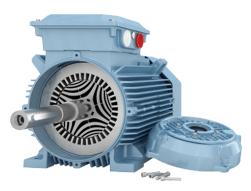
Figure 5: ABB synchronous reluctance motor.
4. Scope of Application
Synchronous reluctance motors have the characteristics of sturdiness, reliability, high efficiency, energy saving, wide speed regulation range and convenient maintenance. There is no permanent magnet on the rotor and no risk of demagnetization, and the efficiency is stable for a long time. It is a cost-effective speed regulation drive solution in the field of AC drive, and meets the speed regulation drive requirements of various industries such as textiles, fans, pumps, conveyor belts, and transportation.
5. Representative products of High-performance Synchronous Reluctance Motors
5.1 ABB Synchronous Reluctance Motor
ABB IE5 M5AL synchronous reluctance motor is one of the representative products at present, which provides IE5 energy efficiency certification. The motor technology does not contain rare earth magnets, but it achieves the performance indicators of permanent magnet motors, and the output power covers 5.5-315kW. ABB's SynRM reduces bearing and winding temperatures, and extends bearing life.
ABB's synchronous reluctance technology combines the performance of a permanent magnet motor with the easy use of an induction motor. The rotor has neither magnets nor windings, and virtually no power losses. Plus, since there is no magnetism in the rotor, its maintenance is easy.
The open-loop control technology required in reluctance synchronous motors is the core technology currently mastered by only a few manufacturers, including Danfoss and ABB. Danfoss has more advantages in the field of high-end inverter open-loop drive reluctance synchronous motor.

Figure 6: ABB synchronous reluctance motor.
5.2 Danfoss Synchronous Reluctance Motor
Danfoss FC300 series replaces traditional asynchronous motors with open-loop synchronous reluctance assist technology, which can achieve 25% energy-saving benefits. With unique synchronous reluctance assisted permanent magnet technology (SRPM), the FC102, FC202, FC302 series develop and produce high performance powertrains for heavy duty vehicles, machines and ships.
Related Info
What is Three Phase Induction Motor and How Does It WorkWhat is Synchronous Motor
Squirrel Cage Induction Motor Vs Wound Rotor Induction Motor: Rotor Structure, Pros and Cons
What is the Difference between Synchronous and Induction Motor
FANUC Spindle Amplifier Alarm Codes and Solutions (4)
