


Figure 1: Programmable logic controllers.
The programmable logic controller (PLC) is a digital operation electronic system specially designed for application in industrial environment. It uses a programmable memory, and executes instructions for operations such as logical operations, sequence control, timing, counting, and arithmetic operations in it. It controls various types of mechanical equipment or production processes through digital or analog input and output.
Basics about the PLC
The PLC is a digital operation controller with microprocessor for automatic control. It can load control instructions into memory at any time for storage and execution. The programmable controller is composed of functional units such as central processing unit (CPU), instruction and data memory, input/output interface, power supply, and digital-to-analog conversion (DAC).
The PLC used in industry is already equivalent to or close to the host of a compact computer, and its advantages in scalability and reliability make it widely used in various industrial control fields. Whether it is in the computer direct control system, the distributed control system (DCS), or the fieldbus control system (FCS), there are always a large number of various types of PLC controllers used.
There are many PLC manufacturers, such as Siemens, Schneider, Mitsubishi, Delta, etc. Almost all manufacturers involved in the field of industrial automation will provide their PLC products.
The Basic Structure of the PLC
The programmable logic controller is essentially a computer dedicated to industrial control, and its hardware structure is basically the same as that of a microcomputer. The basic components of the PLC are CPU, power supply, memory, input module, output module. Its structure is shown in figure 2.

Figure 2: The structure and components of the programmable logic controller.
The Working Mode of the PLC
The basic working mode of the PLC is to execute the user program in sequence, and execute one instruction per clock cycle. The execution of the user program is generally divided into two types: cyclic scanning and timing scanning. The scanning process is divided into three stages: input, execute and output.
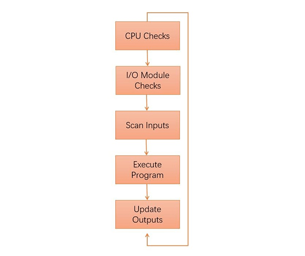
Figure 3: The working mode of the PLC scanning.
1) Input. The PLC reads in the state of all input terminals sequentially in scanning mode, stores it in the input register, and then transfers to the execute stage.
2) Execute. The PLC executes a program one instruction at a time using only the memory copy of the inputs the ladder logic program.
3) Output. After all the instructions are executed, all the output states in the output register are sent to the output circuit to become the actual output of the PLC.
After the PLC executes the above three stages, it is called a scan cycle.
Related Info
How to maintain optical fiber amplifiers?What is an Erbium Doped Fiber Amplifier?
How do Erbium Doped Fiber Amplifiers Work?
What is an Optical Fiber Amplifier?
Classifications and Features of Optical Fiber Amplifiers
