


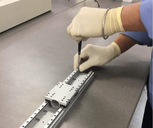
Figure 1: Installing a linear guideway.
When the linear guideway is under load and moves, the surface of the ball track and the steel ball are constantly subjected to cyclic stress. Once it reaches the critical value of rolling fatigue, the contact surface will start to produce fatigue damage, and the peeling phenomenon of fish scale-like flakes will occur on part of the surface, which is called surface peeling. It is extremely important for the definition of the service life of the linear guideway.
When it comes to the service life of linear guideways, there are rated life and service life. The definition of rated life is: The total running distance that a batch of identical products can run under the same conditions and rated load one by one without surface peeling in 90% of them. The definition of life is the total running distance until the surface of the ball track and the steel ball are peeled off due to material fatigue.
The Formula of Service Life Calculation
Relatively ideally, we can calculate the rated life of linear guideway with operating load and basic dynamic rated load:
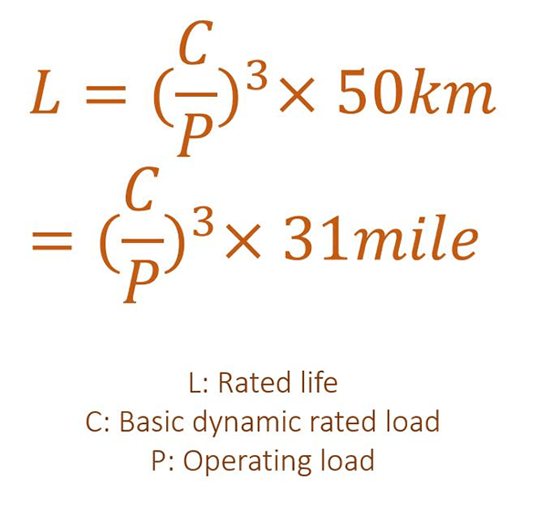
Figure 2: Calculating rated life based on basic dynamic rated load and operating load.
If we take into account other factors like hardness factor (fH), temperature factor (fT), and load factor (fW), which will be explained below, the formula of service life would be:
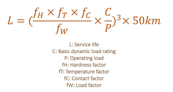
Figure 3: Calculating service life.
Hardness Factor (fH)
The hardness of the contact surface of the ball track of the linear guideway has certain requirements, such as HRC58-62. If it cannot be achieved, the rated load and service life of the linear guideway will be reduced. At this time, the dynamic and static rated loads are the values listed in the dimension table multiplied by the corresponding hardness factor.
For example, the hardness requirements of HIWIN's linear guideways are above HRC58, so its fH is 1.
Temperature Factor (fT)
The system temperature will affect the material of the linear guideway. When the temperature is higher than 100°C (212°F), the rated load and service life of the linear guideway will be reduced. At this time, the dynamic and static rated loads are the values listed in the dimension table multiplied by the corresponding temperature factors. Since some parts are made of plastic and are not resistant to high temperature, it is recommended that the temperature should be lower than 100°C.
Load Factor (fW)
The following table elaborates how to determine the fW according to conditions of use.
| Condition of Use | fw |
| No shocks/vibrations, low speed: 15m/min. or less | 1.0-1.5 |
| No significant shocks/vibrations, medium speed: 60m/min. or less | 1.5-2.0 |
| With shocks/vibrations, high speed: 60m/min. or more | 2.0-3.5 |
Figure 4: Determine the fW according to conditions of use.
The load acting on the linear guideway is not only the self-weight of the device, the inertial load when starting and stopping, and the moment load caused by the suspension, but also the vibration and shock load accompanying the movement.
This type of load is not easy to calculate. According to experience, load conditions and use speed, it is recommended to multiply the calculated load value by the corresponding load factor.
Related Info
Classifications of Linear GuidewaysMaterials for Linear Guideways
Top 7 Linear Guideway Brands
How to Maintain a Linear Guideway?
The Lubrication of the Linear Guideway
