


Figure 1: Common types of diaphragm pump.
1. Oil-free Lubricating Pneumatic Diaphragm Pump

Figure 2: Pneumatic diaphragm.
An oil-free lubricating pneumatic diaphragm pump belongs to the field of pneumatic machinery. It is mainly applicable to food and beverage treatment, chemical process, pharmaceutical oil refining, wastewater treatment and transportation of mud and paper residue.
2. Multi Cylinder Piston Diaphragm Pump
Multi cylinder piston diaphragm pump belongs to plant protection mechanical pumps. Its features are: each cylinder is arranged in a star radial direction, the diaphragm is forced to move back and forth by the piston, which can obtain high pressure, large flow, good stability, and its discharge pressure and flow can be adjusted at will. It can be used for spraying liquid medicine, sprinkling irrigation, environmental disinfection and sterilization, sanitation and epidemic prevention, highway sprinkling, spraying machinery, vehicles, buildings and industrial transmission of liquid, etc.
3. Hydraulic Diaphragm Pump
Hydraulic diaphragm pump is used to transport slurry or liquid materials. It is composed of 2 pump bodies, a diaphragm, a hydraulic reversing valve, a feed pipe, a discharge pipe and a hydraulic power part. The hydraulic reversing valve is a standard three position four-way hydraulic reversing valve with simple structure and no wearing parts. The control hydraulic directional valve is completed by the semi-circular long groove on the pull rod and the annular grooves on both sides. There is no need to set another control valve, so the pump has a long service life and low manufacturing cost.
4. Flow Adjustable Diaphragm Pump
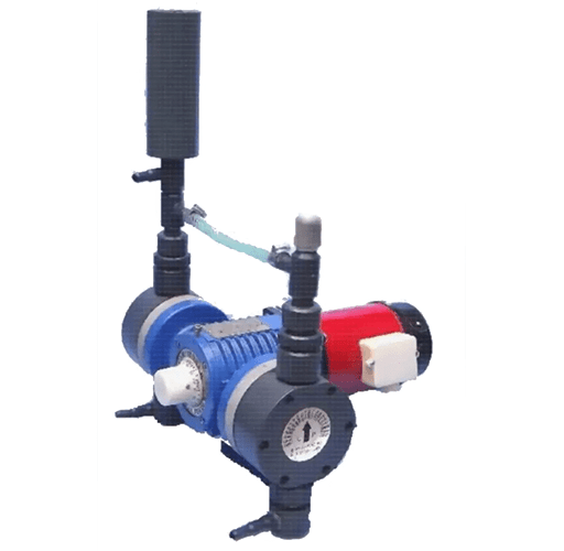
Figure 3: Flow adjustable diaphragm pump.
The flow adjustable diaphragm pump is composed of a motor, a diaphragm pump, a crank connecting rod mechanism and a flow regulating device. The flow regulating device is composed of an eccentric transition shaft, an eccentric shaft, an eccentric shaft rotating disc and a transmission pressing disc, which can adjust the amplitude of the diaphragm and has a scale display. The motor of the utility model can adopt synchronous low speed, which avoids the vibration caused by the existing diaphragm pump when the motor is running at high speed and reduces the noise, At the same time, because the high frequency vibration of the diaphragm is avoided, the working accuracy and service life of the pump are improved.
5. Double Ended Double Pump Body Diaphragm Pump
Double ended double pump body diaphragm pump with buffer chamber for pumping various gases (such as air). It is characterized in that the rotating shaft of the motor extends from two ends to drive a pump body respectively, and the two pump chambers are connected with a buffer chamber to form a double end double pump body diaphragm pump with a buffer chamber. The combined diaphragm pump has large air extraction flow, no pulsation, simple and compact structure and low failure rate. In particular, it has obvious advantages in improving the extraction flow, eliminating air flow pulsation and reducing power consumption.
6. Manual Double Suction Diaphragm Pump
The manual double suction diaphragm pump is composed of left and right pump shells, diaphragms, connecting rods, bellows, inlet (outlet) water pipes, one-way valve plates, etc. The pump shell is clamshell shaped and the diaphragm is corrugated. This kind of pump is light and cheap. Its structure can make the suction and discharge of liquid not limited by directionality, and can reduce the hydraulic curve loss and impact loss, thus significantly improving the work efficiency. It is applicable to the farmland irrigation of families in mountainous areas, low-lying and low ridge liquidity operations, as well as garden irrigation, large-scale irrigation of vegetable gardens in the suburbs of cities and towns.
7. Combined Pneumatic Diaphragm Pump
The combined pneumatic diaphragm pump with lining is characterized in that the inner wall of the shell is provided with a rubber lining integrated with the inner wall by hot pressing, and the radial distance of its inner cavity is 115mm. The check valve is a combined structure, and its upper cover, upper valve body, main valve body, lower valve body and lower cover are successively seated together and fixed with bolts. The side walls of the left and right channel cavities of the upper valve body and the lower valve body are provided with rubber linings that are integrated with the side walls by hot pressing. It is suitable for conveying all kinds of corrosive, viscous or suspended liquids. It has the characteristics of good sealing performance, low cost and long service life, and the maximum flow can reach 50 tons / hour.
8. Hydraulic Tubular Diaphragm Pump

Figure 4: Hydraulic tubular diaphragm pump.
The hydraulic tubular diaphragm pump is a diaphragm pump for conveying chemical slurry, which is characterized in that a limit cylinder is installed in the inner cavity of the cylinder body, a straight pipe diaphragm is installed in the inner cavity of the limit cylinder, and the upper and lower ends of the straight pipe diaphragm are respectively equipped with valve seats, valve rings, valve covers, and pipe cores, which are connected with the cylinder body through the threads on the pipe shell. The mechanical diaphragm, rear sleeve and bracket are overlapped together and connected with the cylinder block through bolts. The push rod is connected with the nut through the central hole of the bracket, back sleeve, support plate and mechanical diaphragm. In addition, there is a double body diaphragm pump with an intermediate medium cavity surrounded by a mechanical diaphragm, a cylinder body and a limit cylinder. The diaphragm pump is driven by an eccentric mechanism and a two-way push rod to vibrate and transport slurry. There is a diaphragm on both sides of the two-way push rod. The motor operates an eccentric shaft, and the circular motion of the eccentric shaft is used to make the two-way push rod move horizontally.
9. Reciprocating Diaphragm Pump
One end of the reciprocating diaphragm pump is provided with a concave flange, the other end is sealed and matched with the end cover, and the liquid inlet and outlet pipe of the end cover is provided with a one-way valve to control the liquid inlet and outlet; a piston, sealing rings on the front and rear sections respectively, a solution chamber at the middle section, and a diaphragm holder on the mandrel cooperates with a pressing plate and a lock nut to compress the diaphragm; The outer edge of the diaphragm is sealed and fixed on the flange by pressure rings and bolts; The spindle end is connected to the drive system. The pump has simple structure and corrosion resistance. And it can work continuously for a long time under high temperature, high pressure and electrochemical environment.
Related Info
What is Diaphragm PumpsHow to Install the Gear Pump
What is a Gear Pump
Classification of Gear Pump
