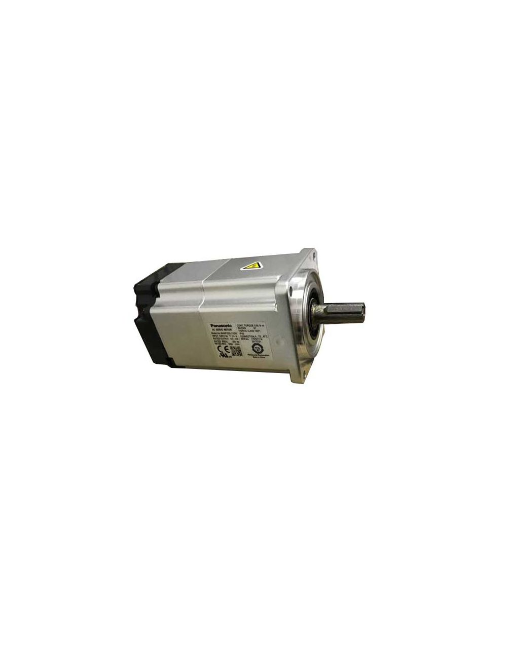
Mitsubishi servo system consists of servo motor, controller, and servo drive (also called servo amplifier), mainly including MR-J2S series, MR-J series, MR-H series, MR-C series, MR-J2 series, MR-J2S series, MR-E series, MR-J3 series, MR-ES series, MR-JE series, MR-J4 series, etc.
1. Common Mitsubishi Servo Amplifier Alarms and Troubleshooting
Usually the fault type of Mitsubishi servo drive can be judged by the alarm code:
1.1 AL.E6 - Servo Forced Stop Warning
There are generally two reasons for this fault. One is that the control circuit is not connected to the 24V power supply, and the other is that EM2/EM1 (forced stop) is turned off.
1.2 AL.37 - Parameter Error
Cause Analysis:
The internal parameters are chaotic, the operator mistakenly sets the parameters, or the drive is subject to external interference.
Troubleshooting Methods:
Generally, the problem can be solved by restoring the parameters to factory settings.
1.3 AL.16 - Encoder Error
Fault Analysis: Communication abnormality between servo encoder and Mitsubishi servo amplifier.
Cause Analysis:
① Connector CN2 is not connected properly;
② Mitsubishi servo encoder failure;
③ Mitsubishi servo encoder cable failure (open circuit or short circuit).
Troubleshooting Methods:
① Wire Correctly;
② Replace the Mitsubishi servo encoder or Mitsubishi servo motor;
③ Repair or replace the Mitsubishi servo cable.
1.4 AL.20 - Encoder Error
Cause Analysis:
Motor encoder failure, cable disconnection, loose connector, etc.
Troubleshooting Methods:
Replace the encoder cable or servo motor encoder. When this fault occurs in the MR-J3 series, another possibility is that the ground wire of the drive CPU is burned out.
1.5 AL.30 - Regenerative Error
If an alarm occurs just after power is turned on, the internal braking circuit components of the drive are damaged. If it occurs during operation, check the wiring of the braking circuit and install an external braking resistor if necessary.
1.6 AL.32 - Overcurrent
Fault Analysis: The output current of the servo amplifier exceeds the allowable current, which is referred to as overcurrent.
Cause Analysis:
① There is a short circuit in the U·V·W phase on the output side of the Mitsubishi servo amplifier;
② The U·V·W phase on the output side of the Mitsubishi servo amplifier is grounded;
③ Due to interference from external noise, an error occurs in the overcurrent detection circuit;
④ The servo amplifier transistor (IPM) is faulty.
Troubleshooting Methods:
① Connect the lines accurately;
② Connect the lines accurately;
③ Implement anti-interference processing;
④ Replace the Mitsubishi servo amplifier.
1.7 AL.33 - Overvoltage
Cause Analysis:
① The wiring of the built-in regenerative braking resistor or regenerative braking option is broken or has poor contact;
② Regenerative braking transistor failure;
③The capacity of the built-in regenerative braking resistor or regenerative braking option is insufficient.
Troubleshooting Methods:
① Connect the wires correctly after replacing the wires;
② Replace the Mitsubishi servo amplifier;
③ Use the regenerative braking option or replace it with a large-capacity regenerative braking option.
1.8 AL.35 - Command Frequency Error
Fault Analysis: The frequency of the input command pulse is abnormal, and usually the frequency is too high.
Cause Analysis:
① The command pulse frequency is too high;
② The command pulse is mixed with noise;
③ Command device failure.
Troubleshooting Methods:
① Change the command pulse frequency to reach an appropriate value;
② Implement anti-interference processing;
③ Replace the command device.
1.9 AL.50 - Overload
Cause Analysis:
① The actual load is greater than the continuous output load capacity of Mitsubishi servo amplifier;
② Mitsubishi servo system is unstable and vibrates;
③ Mechanical failure;
④ The output U, V, and W phases of the Mitsubishi servo amplifier and the input U, V, and W phases of the Mitsubishi servo motor are not connected correctly;
⑤ Mitsubishi servo encoder failure.
Troubleshooting Methods:
① Reduce the load or replace with a more powerful Mitsubishi servo motor;
② Adjust and modify the gain of the servo motor;
③ Check the operating mode and install the limit switch;
④ Wire correctly;
⑤ Replace the Mitsubishi servo encoder or Mitsubishi servo motor.
1.10 AL.31.1 - Motor Overspeed Alarm
Cause Analysis:
① The input command pulse frequency is too high;
② The acceleration and deceleration time is too short, resulting in excessive overshoot;
③ The Mitsubishi servo system is unstable;
④ The electronic gear ratio is too large;
⑤ The Mitsubishi servo encoder fails, etc.
Troubleshooting Methods:
① Set the correct pulse frequency;
② Increase the acceleration and deceleration time constant;
③ Reset the gain;
④ and set the correct electronic gear ratio;
⑤ Replace the encoder.
2. Mitsubishi Servo Drive Alarm Code List: Quick Fix Mitsubishi Servo Drive Error
|
Alarm / warning No. |
Name |
|
Alarm / warning No. |
Name |
|
10 |
Undervoltage |
|
7A |
Parameter setting error (safety observation function) |
|
11 |
Switch setting error |
|
7B |
Encoder diagnosis error (safety observation function) |
|
12 |
Memory error 1 (RAM) |
|
7C |
Functional safety unit communication diagnosis error (safety observation function) |
|
13 |
Clock error |
|
7D |
Safety observation Error |
|
14 |
Control process error |
|
82 |
Master-slave operation error 1 |
|
15 |
Memory error 2 (EEP-ROM)
|
|
84 |
Network module initialization error |
|
16 |
Encoder initial communication error 1 |
|
85 |
Network module error |
|
17 |
Board error |
|
86 |
Network communication error |
|
19 |
Memory error 3 (Flash-ROM) |
|
8A |
USB communication time-out error/ serial communication time-out error/ Modbus RTU communication time-out error |
|
1A |
Servo motor combination error |
|
8C |
Network module communication error |
|
1B |
Converter error |
|
8D |
CC-Link IE communication error |
|
1E |
Encoder initial communication error 2 |
|
8E |
USB communication error/serial communication error/Modbus RTU communication error |
|
1F |
Encoder initial communication error 3 |
|
88888 |
Watchdog |
|
20 / 21 |
Encoder error |
|
90 |
Home position return incomplete warning |
|
24 |
Main circuit error |
|
91 |
Servo amplifier overheat warning (Note 1) |
|
25 |
Absolute position erased |
|
92 |
Battery cable disconnection warning |
|
27 |
Initial magnetic pole detection error |
|
93 |
ABS data transfer warning |
|
28 |
Linear encoder error 2 |
|
96 |
Home position setting warning |
|
2A |
Linear encoder error 1 |
|
97 |
Positioning specification warning |
|
2B |
Encoder counter error |
|
98 |
Software limit warning |
|
30 |
Regenerative error |
|
99 |
Stroke limit warning |
|
31 |
Overspeed |
|
9A |
Optional unit input data error warning |
|
32 |
Overcurrent |
|
9B |
Error excessive warning |
|
33 |
Overvoltage |
|
9C |
Converter error |
|
34 |
SSCNET receive error 1 |
|
9D |
CC-Link IE warning 1 |
|
35 |
Command frequency error |
|
9E |
CC-Link IE warning 2 |
|
36 |
SSCNET receive error 2 |
|
9F |
Battery warning |
|
37 |
Parameter error |
|
E0 |
Excessive regeneration warning |
|
39 |
Program error |
|
E1 |
Overload warning 1
|
|
3A |
Inrush current suppression circuit error |
|
E2 |
Servo motor overheat warning |
|
3D |
Parameter setting error for driver communication |
|
E3 |
Absolute position counter warning |
|
3E |
Operation mode error |
|
E4 |
Parameter warning |
|
42 |
Servo control error (for linear servo motor and direct drive motor) / Fully closed loop control error (for fully closed loop control) |
|
E5 |
ABS time-out warning |
|
45 |
Main circuit device overheat |
|
E6 |
Servo forced stop warning |
|
46 |
Servo motor overheat |
|
E7 |
Controller forced stop warning |
|
47 |
Cooling fan error |
|
E8 |
Cooling fan speed reduction warning |
|
50 |
Overload 1 |
|
E9 |
Main circuit off warning |
|
51 |
Overload 2 |
|
EA |
ABS servo-on warning EB The other axis error warning |
|
54 |
Oscillation detection |
|
EC |
Overload warning 2 |
|
56 |
Forced stop error |
|
ED |
Output watt excess warning |
|
61 |
Operation error unit setting error |
|
F0 |
Tough drive warning |
|
63 |
STO timing error |
|
F2 |
Drive recorder - Miswriting warning |
|
64 |
Functional safety |
|
F3 |
Oscillation detection warning |
|
65 |
Functional safety unit connection error |
|
F4 |
Positioning warning |
|
66 |
Encoder initial communication error (safety observation function) |
|
F5 |
Simple cam function - Cam data miswriting warning |
|
67 |
Encoder normal communication error 1 (safety observation function) |
|
F6 |
Simple cam function - Cam control warning |
|
68 |
STO diagnosis error |
|
F7 |
Machine diagnosis warning |
|
69 |
Command error |
|
74 |
Option card error 1 |
|
70 |
Load-side encoder initial communication error 1 |
|
75 |
Option card error 2 |
|
71 |
Load-side encoder normal communication error 1 |
|
79 |
Functional safety unit diagnosis error |
|
72 |
Load-side encoder normal communication error 2 |
|
|
3. Conclusion
During daily use, Mitsubishi servo drives may stop working due to various reasons such as improper operation or equipment failure. At this time, follow the Mitsubishi servo drive alarm code list to confirm the cause of the fault and then solve it.
Before installing, using, repairing, and inspecting the servo amplifier, we must fully understand its technical data and instructions for use, as well as the servo motor data set and accompanying data. Improper operation and use may cause machine failure and personal injury.
The above are some common Mitsubishi servo drive alarm codes and troubleshooting methods. Hope that they can help you quickly detect machine failures in production.