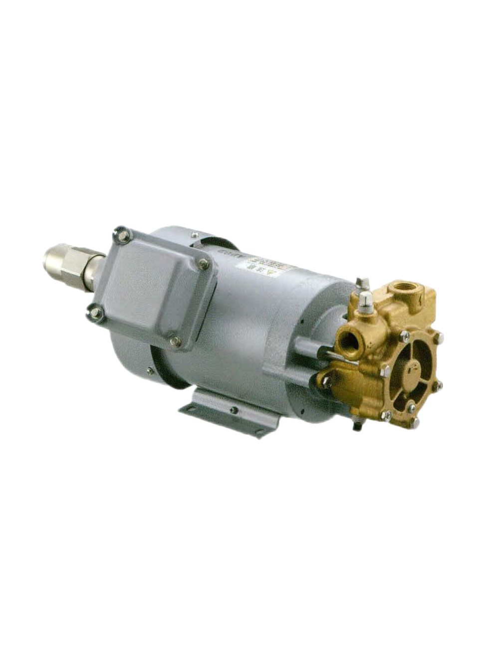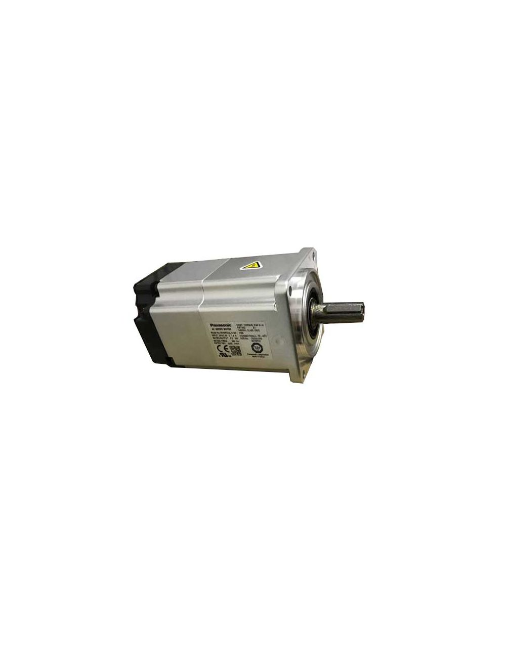
Figure 1: Stepper motor, servo motor, and traditional motor.
The following introduces the working principle, structure, types and application of the three major control methods of servo, step and variable frequency.
1. Servo Control
1.1 How AC Servo Motor Work
The rotor inside the servo motor is made of a permanent magnet. The U/V/W three-phase electricity controlled by the servo drive forms an electromagnetic field. The rotor rotates under the action of this magnetic field.
At the same time, the encoder of the motor gives a feedback signal to the drive. The driver compares the feedback value with the target value and adjusts the angle of rotation of the rotor. The accuracy of the servo motor depends on the accuracy (number of lines) of the encoder.
1.2 Servo System Structure

Figure 2: Servo system structure diagram.
1.3 Composition and Types of Servo Systems
Composition:
Servo system is a general term for control systems that use position and angle as control variables. Systems in which speed, angular velocity, acceleration, force, etc. associated with position and angle are control variables are also included in the servo system.
Types:
1. According to the control system structure, it is divided into: open loop type and closed loop type.
2. According to the types of driving components, it is divided into:
a. Stepper motor servo system.
b. DC motor servo system.
c. AC motor servo system.
1.4 Characteristics of Servo Motor (AC)
1. High positioning accuracy.
2. Fast response time.
3. Convenient and flexible control.
4. Many models can be selected according to different application environments.
5. Fully closed-loop control, monitoring operating conditions in a timely manner and making appropriate adjustments.
1.5 Servo Control Applications
➤Small servo motor series:
Low inertia: belt drives, robots, assembly, sewing machines, X-Y tables, food machinery, etc.
Ultra-low inertia: plug-in, assembly.
➤Medium servo motor series:
Medium inertia: conveyor, robot, X-Y table.
Low inertia: high frequency position control.
➤Flat servo motor series: Due to its flat shape, it is ideal for installation in situations where space is limited, such as machinery factories and food machinery.

Figure 3: Servo motor application.
2. Step Control
2.1 How Stepper Motors Work
A stepper motor is an actuator that converts electrical pulses into angular displacement. When the stepper driver receives a pulse signal, it drives the stepper motor to rotate a fixed angle (called "step angle") in the set direction, and its rotation runs step by step at a fixed angle.
The angular displacement can be controlled by controlling the number of pulses to achieve accurate positioning. At the same time, the speed and acceleration of the motor rotation can be controlled by controlling the pulse frequency, thereby achieving the purpose of speed regulation.
The stepper motor can be used as a special motor for control. It is widely used in various open-loop controls by taking advantage of its characteristics of non-accumulative errors (accuracy of 100%).
2.2 Stepper Motor System

Figure 4: Stepper control system.
2.3 Stepper Motor Types
The more commonly used stepper motors now include variable reluctance stepper motor (VR), permanent magnet stepper motors (PM), hybrid stepper motors (HB / HY) and single-phase stepper motors.
●PM stepper motors are generally two-phase, with small torque and volume, and the step angle is generally 7.5 degrees or 15 degrees.
●VR stepper motors are generally three-phase and can achieve large torque output. The step angle is generally 1.5 degrees, but the noise and vibration are large. The rotor magnetic circuit of the VR stepper motor is made of soft magnetic materials, and the stator has multi-phase excitation windings that use changes in magnetic permeability to generate torque.
●Hybrid stepper motor combines the advantages of PM type and VR type. It is divided into two phases and five phases: the two-phase step angle is generally 1.8 degrees and the five-phase step angle is generally 0.72 degrees. This type of stepper motor is the most widely used.

Figure 5: Hybrid stepper motor.
2.4 Characteristics of Stepper Motor
1. Generally, the accuracy of stepper motors is 3-5% of the step angle and is not cumulative.
2. The maximum temperature allowed on the surface of a stepper motor is generally above 130 degrees Celsius.
3. The torque of the stepper motor will decrease as the speed increases.
4. The stepper motor can run normally at low speed, but if it is higher than a certain speed, it will not start and will make a whistling sound.
5. Stepper motors are used in low-speed situations---the speed does not exceed 1,000 rpm.
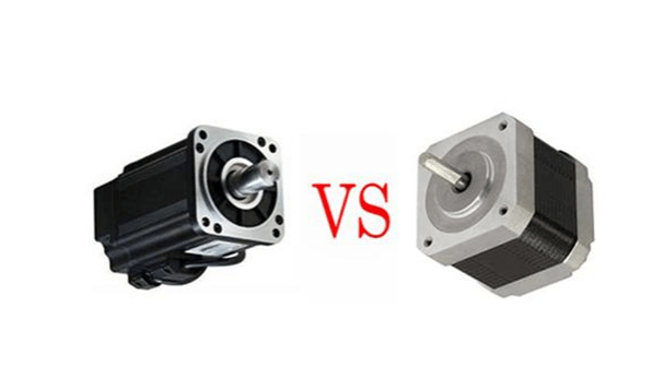
3. Servo Motor vs. Stepper Motor: Performance Comparison of the Two Motors
Figure 6: Servo motor vs. Stepper motor.
1. Different Control Accuracy
The step angle of the five-phase hybrid stepper motor is generally 0.72° and 0.36°. The control accuracy of the AC servo motor is guaranteed by the rotary encoder at the rear end of the motor shaft. For a servo motor with a standard 2500-line encoder, its pulse equivalent is 360°/10000=0.036°. The servo motor has higher accuracy than the stepper motor.
2. Different Low-Frequency Characteristics
Stepper motors are prone to low-frequency vibration at low speeds. The AC servo motor runs very smoothly and does not vibrate even at low speeds.
3. Different Overload Capabilities.
Stepper motors generally do not have overload capabilities while AC servo motors have strong overload capabilities.
4. Different Operating Performance
The control of the stepper motor is open-loop control. If the starting frequency is too high or the load is too large, the stepper motor is easy to lose steps or stall. If the motor speed is too high when stopping, the position overshoot is easy to occur.
The AC servo drive system is a closed-loop control and the drive can directly sample the motor encoder feedback signal, internally constituting a position loop and a speed loop. Generally, there will be no loss of steps or overshoot like a stepper motor, and the control performance is more reliable.
5. Different Speed Response Performance
It takes 200 to 400 milliseconds for a stepper motor to accelerate from standstill to operating speed (generally several hundred revolutions per minute).
The AC servo system has good acceleration performance. Taking the Panasonic MSMA 400W AC servo motor as an example, it only takes a few milliseconds to accelerate from standstill to its rated speed of 3000RPM. The servo motor can be used in control situations that require quick start and stop.
6. Different Torque-Frequency Characteristics
The output torque of a stepper motor decreases as the speed increases, and drops sharply at a relatively high speed. The AC servo motor has a constant torque output.
To sum up, AC servo systems are superior to stepper motors in many performance aspects. However, in some situations with low requirements, stepper motors are often used. Therefore, in the design process of the control system, various factors such as control requirements and cost must be comprehensively considered to select an appropriate control motor.

Figure 7: Stepper motor vs. Servo motor.
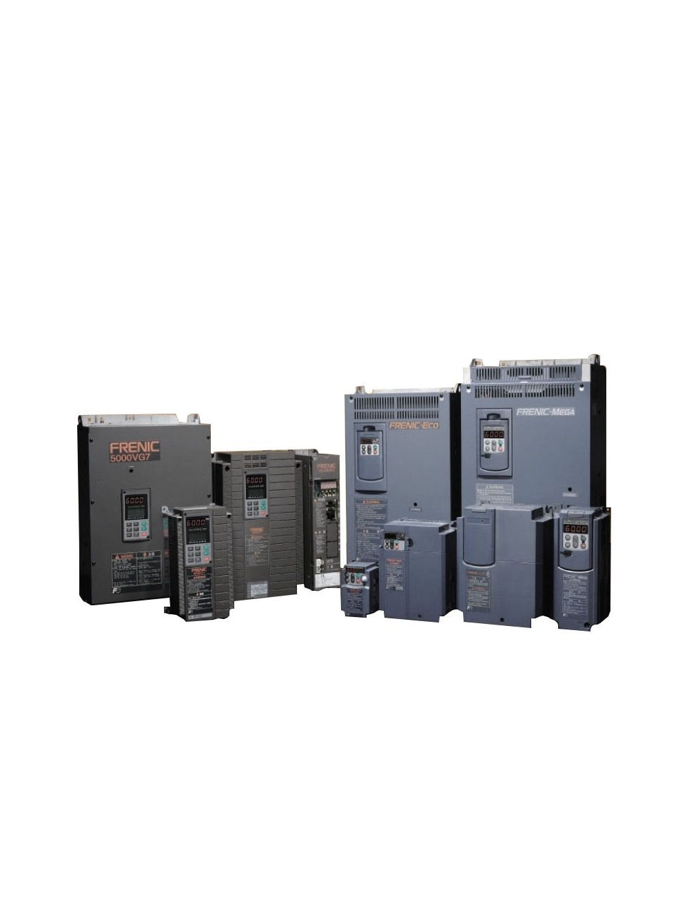
4. Frequency Control
4.1 Principle and Composition of Frequency Converter
The frequency converter is a control device that can easily and freely change the speed of an AC motor. Here's how to change the speed of an AC motor. The frequency converter achieves speed regulation by changing the AC motor power frequency:
n=(120×f)/p
Where
n=motor synchronous speed
f = frequency of electrical power supply
p = number of poles
The composition of the frequency converter is as follows:

Figure 8: The components of the frequency converter.
The working principle of the frequency converter is mainly based on AC-DC-AC (AC-DC-AC) conversion technology. The specific process is as follows:
●AC input: First, the frequency converter receives AC power from the grid.
●Rectification: A rectifier converts incoming AC power into DC power.
●Filtering: The filter removes the voltage fluctuation after rectification and stabilizes the voltage.
●Pulse width modulation (PWM): The pulse width modulator adjusts the pulse width of DC power according to the input control signal and certain rules, thereby changing the frequency and amplitude of the output voltage.
●Inverting: An inverter converts adjusted DC power into AC power with adjustable frequency and voltage.
●Output: The controller adjusts the output of the inverter according to the set control strategy to achieve precise control of the motor speed.
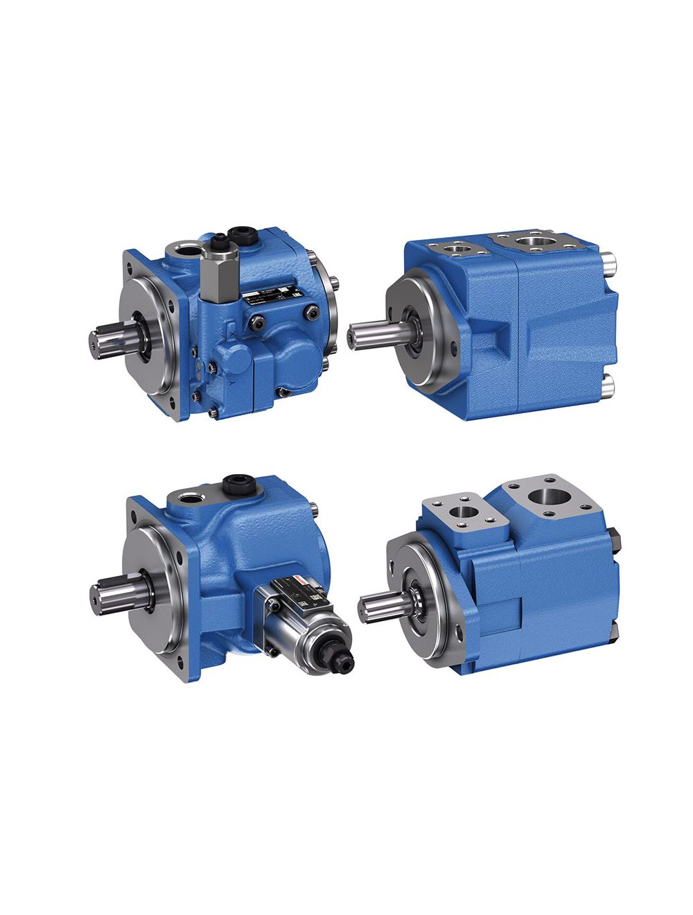
4.2 Introduction to General Variable Frequency Motors
A 3 phase squirrel cage AC motor is the most common type of induction motor. Its structure and characteristics are as follows:

Figure 9: Structural diagram of 3-phase squirrel cage motor.
4.3 Application of Frequency Converter
The adjustable speed transmission composed of frequency converter and AC motor is called frequency converter transmission, and its functions and uses are as follows. This table is for reference only.
|
Function |
Application |
Key technology |
Applicable frequency converter |
|
|
1 |
Energy saving |
Fan, blower, pump |
Improve operational reliability Control and speed adjustment for multiple motors |
General frequency converter |
|
2 |
Improve productivity |
Cranes, automatic warehouses, injection molding machines, conveyor belts |
Speed regulation Improve reliability Smooth operation to prevent slipping |
General frequency converter Special frequency converter Special software
|
|
3 |
Improve product quality |
Machine tools, paper, film, steel plate processing |
Smooth acceleration and deceleration Speed regulation Torque control Positioning control |
General frequency converter Engineering frequency converter |
|
4 |
Equipment rationalization Save maintenance Factory automation |
Fiber machinery, paper, film, steel plate processing |
Increased speed of existing equipment Torque control Unified control of multiple motors Improve reliability |
General frequency converter Engineering frequency converter |
|
5 |
Improve the environment Resistant to harsh environments |
Air conditioner, elevator |
Reduce noise Smooth acceleration and deceleration Explosion proof Safety |
General frequency converter Engineering frequency converter Special frequency converter |
Table 1: Functions and uses of frequency converter.